Objective
To verify the consistency of results for models of different dimensions.
Reference
M. Courtand et P. Lebelle, Formulaire du beton arme, t.2, Paris, Eyrolles,1976, p. 382.
Problem statement
To determine the displacements of the free end x, y, z and the maximum stress σz in the fixed cross-section.

|
|
|
|
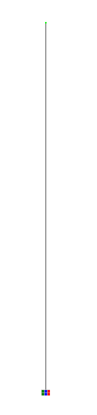
Bar model
|
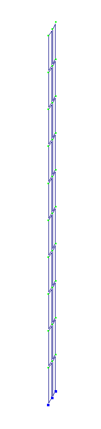
Shell model
|
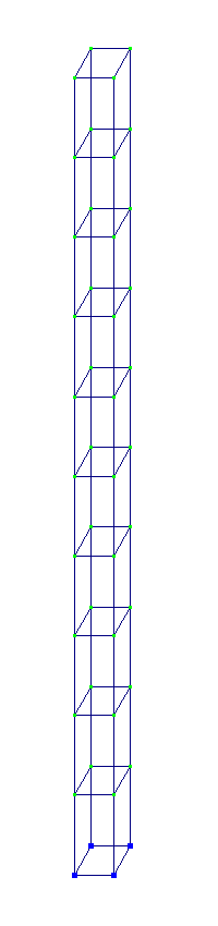
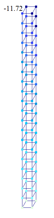
Solid model
|
Height of cantilever bar l = 10 m
Dimensions of the cross-section of the cantilever bar b = h = 0,5 m
Material properties
Modulus of elasticity ' = 3 * 107 kPa
Poisson's ratio μ = 0,2
Loads
Concentrated load along the X‑axis of the global coordinate system Px = 10 kN
Concentrated load along the Y‑axis of the global coordinate system Py = 10 kN
Concentrated load along the Z‑axis of the global coordinate system N = 10000 kN (Load case 3)
Note
Design model: model type 5 (6 DOF per node).
Three design models are considered:
Bar model ' 2 elements, FE type 5, 3 nodes;
Shell model ' 20 elements, FE type 50, 85 nodes;
Solid model ' 10 elements, FE type 37, 128 nodes.
Output data
|
|
|
|
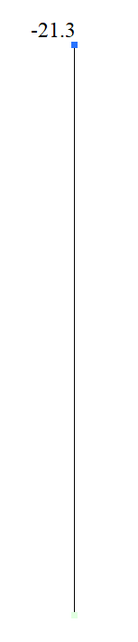
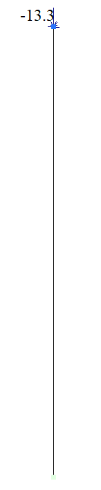
Displacement values x, y, z in the bar model (mm)
|
||
|
|
|
|
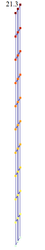
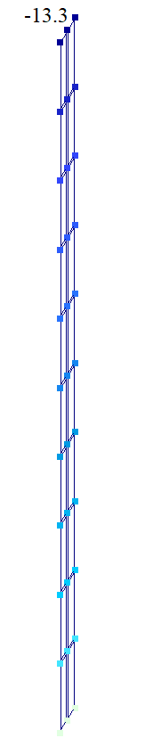
Displacement values x, y, z in the shell model (mm)
|
||
|
|
|
|
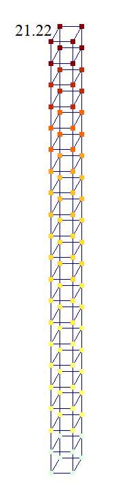
Displacement values x, y, z in the solid model (mm)
|
||
Comparison of calculation results
| Model | Load case 1 | ||||
|---|---|---|---|---|---|
| Displacement x, y, z (mm) | Error, % | Stress σz (kPa) | Error, % | ||
| Bar | 21,33 | 0 | 4781 | 0,3 | |
| Shell | 21,25 | 0,58 | 5100 | 6,25 | |
| Solid | 21,21 | 0,57 | 4923 | 2,56 | |
| Analytical solution | 21,333 | - | 4800 | - | |
| Model | Load case 2 | ||||
|---|---|---|---|---|---|
| Displacement x, y, z (mm) | Error, % | Stress σz (kPa) | Error, % | ||
| Bar | 21,33 | 0 | 4781 | 0,39 | |
| Shell | 21,31 | 0,107 | 4845 | 0,9 | |
| Solid | 21,21 | 0,57 | 4923 | 2,56 | |
| Analytical solution | 21,333 | - | 4800 | - | |
| Model | Load case 3 | ||||
|---|---|---|---|---|---|
| Displacement x, y, z (mm) | Error, % | Stress σz (kPa) | Error, % | ||
| Bar | -13,33 | 0 | -40000 | 0 | |
| Shell | -13,33 | 0 | -40000 | 0 | |
| Solid | -13,31 | 0,15 | -40000 | 0 | |
| Analytical solution | -13,33 | - | -40000 | - | |
Download verification test
If you find a mistake and want to inform us about it, select the mistake, then hold down the CTRL key and click ENTER.
Comments